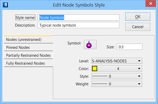
| Edit Note Symbols dialog key in fields |
- Style Name — Displays style name. If you are editing the selected node symbols style, this field is display only. If you are creating a new style or copying an existing style, this field can be edited.
- Description — Enter a description for this node style. The description will appear next to the style name in the Node Symbols Style Manager dialog.
|
| Node type tabs |
Each tab in the dialog lets you edit a different node type:
- Nodes (unrestrained) — Maintains the settings for unrestrained nodes. Unrestrained or free nodes are completely unrestricted in X, Y, Z, RX, RY, and RZ.
- Pinned Nodes — Maintains the settings for pinned nodes. Pinned nodes are fully restricted in X, Y, Z, and are completely unrestricted in RX, RY, and RZ.
- Partially Restrained Nodes — Maintains the settings for partially restrained nodes. Partially restrained nodes have any settings that do not fall into the unrestrained, pinned, or fully restrained settings.
- Fully Restrained Nodes — Maintains the settings for fully restrained nodes. Fully restrained nodes are fully restricted in X, Y, Z, RX, RY, and RZ.
|
| Node Symbols |
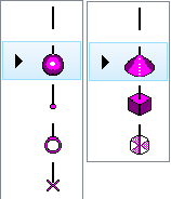
Click the symbol at the top of the node symbol setting to select the shape of the symbol for that node type.
- None — (Represented by a straight line with no terminating symbol.) Available for unrestrained, pinned, partially restrained, and fully restrained node symbols. No other node symbology settings applicable.
- Sphere — Available only for unrestrained node symbols. Default value for unrestrained node symbols.
- Point — Available only for unrestrained node symbols.
- Circle — Available only for unrestrained node symbols.
- X — Available only for unrestrained node symbols.
- Cone — Available for pinned, partially restrained, and fully restrained node symbols. Default for pinned node symbols.
- Solid — Available for pinned, partially restrained, and fully restrained node symbols. Default for fully restrained node symbols.
- Pies — Available for pinned, partially restrained, and fully restrained node symbols. Default for partially restrained node symbols.
|
| Node symbology |
- Size — Enter the size in working units for the display of the node symbol.
- Level — Select the level on which the node symbol will appear.
- Color — Select the color for the node symbol. For a Pie symbol, the color is the outline of the pie wedge that represents the restraint direction.
- Style — Select the line style for the node symbol.
- Weight — Select the line weight for the node symbol.
- Fill Color — Available only with a Pie symbol. Select the color to fill in the pie wedge that represents the restraint direction. The Color field represents the outline, and this Fill Color represents the filled piece.
|
| dialog controls |
- OK — Applies your changes on all tabs and closes the dialog.
- Cancel — Dismisses the dialog without saving changes on any tab.
|